
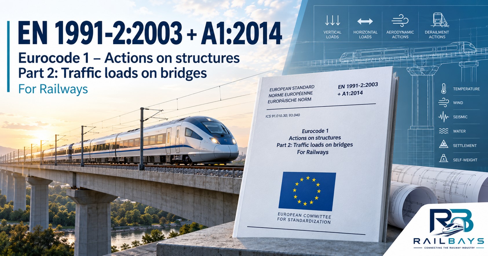
Overview
For railway bridges, the standard covers Load Model 71 (LM71) for normal rail traffic, SW/0 for certain effects on continuous bridges, SW/2 for heavy rail traffic, and the HSLM framework for high-speed dynamic assessment. It also addresses dynamic amplification, centrifugal and nosing forces, traction and braking, multiple-track loading, aerodynamic effects, derailment, fatigue, deck deformation, vibration and passenger comfort.
For high-speed rail, the standard is particularly important because bridge design must consider not only structural strength but also train–track–bridge dynamic interaction, resonance, deck acceleration, track geometry and operational performance.
It should be applied together with EN 1990, the relevant structural Eurocodes, the applicable National Annex, and project/infrastructure-manager requirements.
Purpose
To define the traffic load models, dynamic effects, horizontal forces and accidental actions required for the safe structural design of road, pedestrian and railway bridges, including the effects of normal and high-speed railway traffic
Scope
Covers traffic actions on road bridges, footbridges and railway bridges, including vertical traffic loads, dynamic effects, braking and traction forces, centrifugal and lateral forces, fatigue, aerodynamic effects and accidental actions such as derailment. For railway bridges, it includes LM71, SW/0, SW/2 and high-speed load models (HSLM) and associated structural and serviceability requirements.
EN 1991-2 provides traffic actions to be used primarily with the Eurocode basis of design and the relevant structural material Eurocodes. Traffic loads are treated as actions on the structure, rather than as detailed simulations of individual vehicles or trains.
For railway engineering in particular, an important distinction is made between:
vertical rail traffic loading;
dynamic amplification;
horizontal forces arising from railway operation;
centrifugal effects on curved track;
traction and braking;
nosing forces;
aerodynamic effects from passing trains;
derailment/accidental situations; and
interaction between railway traffic loading and the bridge/track system.
The National Annex is important because EN 1991-2 contains a number of Nationally Determined Parameters (NDPs).
Engineering Overview & Illustrations
Supporting engineering explanation, diagrams and visual references for understanding and applying this railway standard.
EN 1991-2:2003+A1:2014 is Eurocode 1 — Actions on structures — Part 2: Traffic loads on bridges. It sets out how road, pedestrian and railway traffic actions are represented for the structural design of bridges and associated structures.
A detailed summary should cover road traffic load models, pedestrian/cycle actions, railway Load Models 71/SW/0/SW/2, dynamic effects, centrifugal and nosing forces, traction/braking, derailment, aerodynamic actions, load distribution and combinations. Because this is a copyrighted standard, I can summarize its technical requirements and explain how to apply them, but not reproduce substantial portions verbatim.
The standard can broadly be viewed as covering three traffic environments:
| Area | Main subject |
|---|---|
| Road bridges | Cars, lorries and abnormal/heavy vehicles |
| Footbridges | Pedestrians, cyclists and crowd loading |
| Railway bridges | Trains, track loads and railway-specific dynamic/horizontal actions |
Railway traffic load groups
A railway vehicle simultaneously produces several effects:
- vertical loading;
- centrifugal force;
- nosing;
- traction/braking; etc.
However, it would generally be overly conservative or physically inconsistent simply to apply every maximum action simultaneously.
EN 1991-2 therefore establishes groups of railway traffic loads.
1 – Railway vertical loading
The Eurocode does not require every real train operating on a railway to be modelled individually for normal bridge design. Instead, standardised load models are used to represent traffic effects.
The principal railway models include:
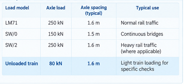
1.1 Load Model 71 — LM71
LM71 is the fundamental railway load model representing normal rail traffic.
Conceptually it consists of concentrated axle loads combined with uniformly distributed loading on either side.
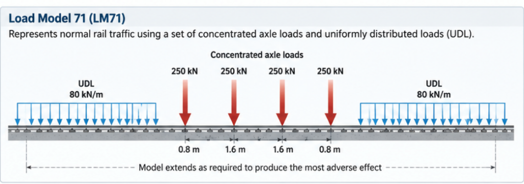
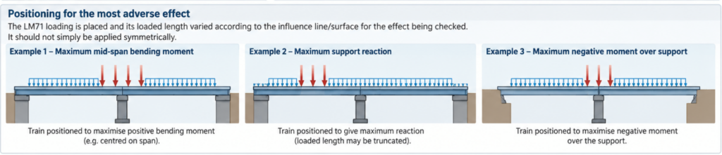
This is important: LM71 should not simply be placed symmetrically on the bridge. Its position and loaded length are varied according to the influence line/surface for the effect being investigated.
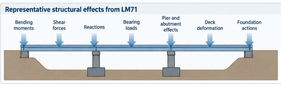
Its purpose is to generate representative structural effects such as:
- bending moments;
- shear forces;
- reactions;
- bearing loads;
- pier and abutment effects;
- deck deformation; and
- foundation actions.
The loading is positioned on the structure to produce the most adverse effect for the particular member or response being checked.
Classification factor α
Railway routes do not necessarily have identical loading requirements. EN 1991-2 therefore provides for the application of a classification factor, α, to specified railway load effects.
Conceptually: Design railway loading = standard load model × route classification factor
This allows infrastructure owners and national authorities to account for routes requiring higher or lower load capacity than the nominal Eurocode model.The applicable α value should therefore be confirmed against:
- the National Annex;
- infrastructure manager requirements;
- project Employer’s Requirements; and
- route classification requirements.
For a high-speed railway project, it should not automatically be assumed that α = 1.0 merely because LM71 is being used.
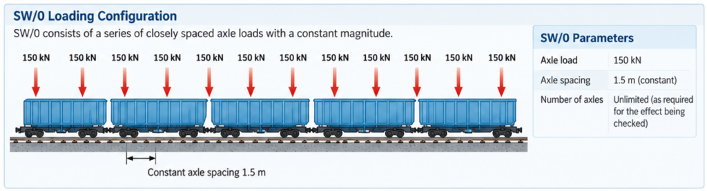
1.2 Load Model SW/0
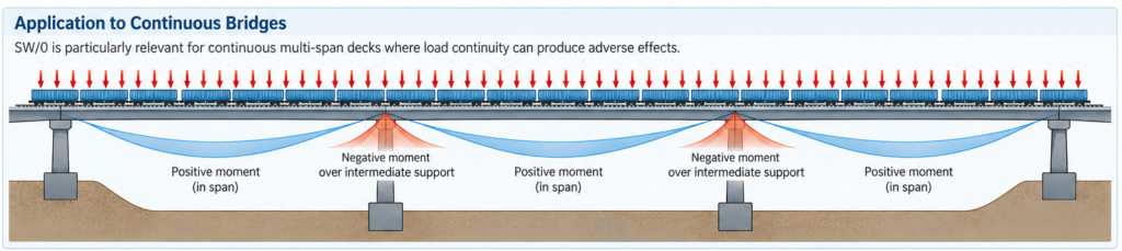
SW/0 is intended particularly to address vertical loading effects associated with continuous bridges.Continuous structures can develop adverse effects that are not necessarily enveloped adequately by a straightforward application of LM71.SW/0 therefore becomes particularly relevant when checking:
- continuous multi-span decks;
- negative moments over intermediate supports;
- support reactions; and
- other effects influenced by the continuity of the structural system.
1.3 Load Model SW/2
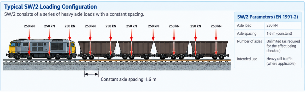
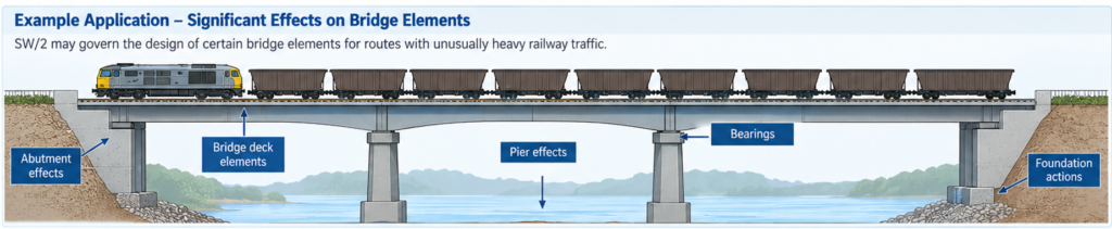
SW/2 represents heavy rail traffic.It is not simply another normal operating train model. Its applicability depends upon the route and project requirements.For routes intended to carry unusually heavy railway traffic, SW/2 may govern particular:
- bridge elements;
- bearings;
- piers;
- abutments; or
- foundations.
Whether SW/2 must be considered should therefore be established at the project/route level.
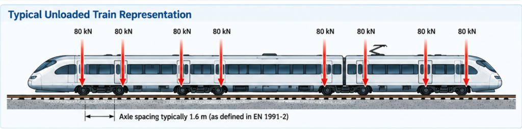
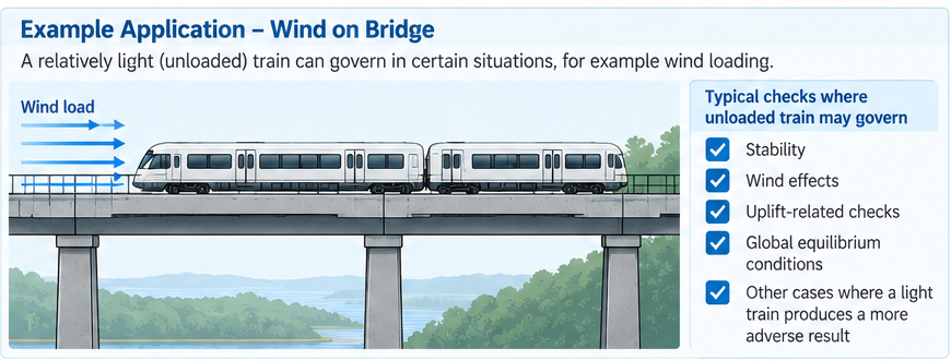
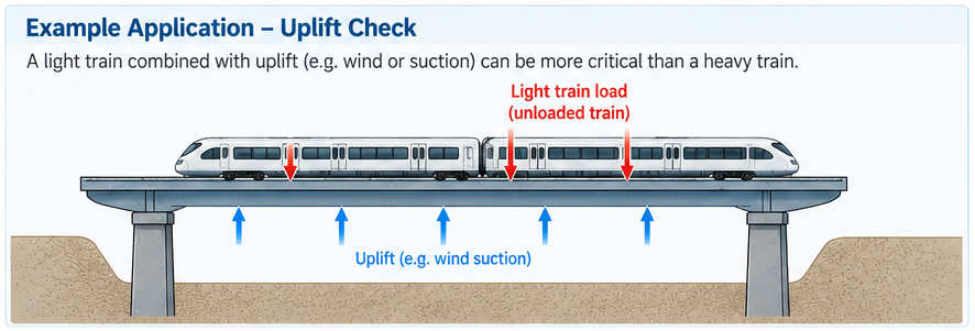
1.4 Unloaded train
The Eurocode also defines an unloaded train representation.This is relevant where a relatively light train loading can produce an adverse result when combined with other actions.Typical examples can involve:
- stability;
- wind;
- uplift-related checks; and
- particular global equilibrium conditions.
It illustrates an important Eurocode principle: maximum vertical railway loading is not necessarily the critical condition for every verification.
1.5 Comparison of Vertical loads
1.6 Eccentricity of vertical railway loading
Railway loading cannot always be assumed to act perfectly symmetrically about the track centreline.The standard addresses eccentric loading resulting from differences in wheel loading and track position.
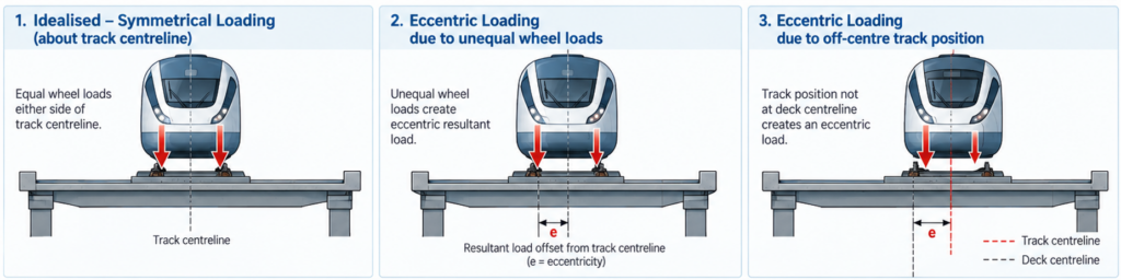
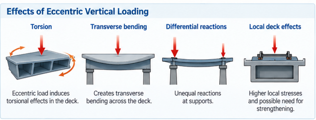
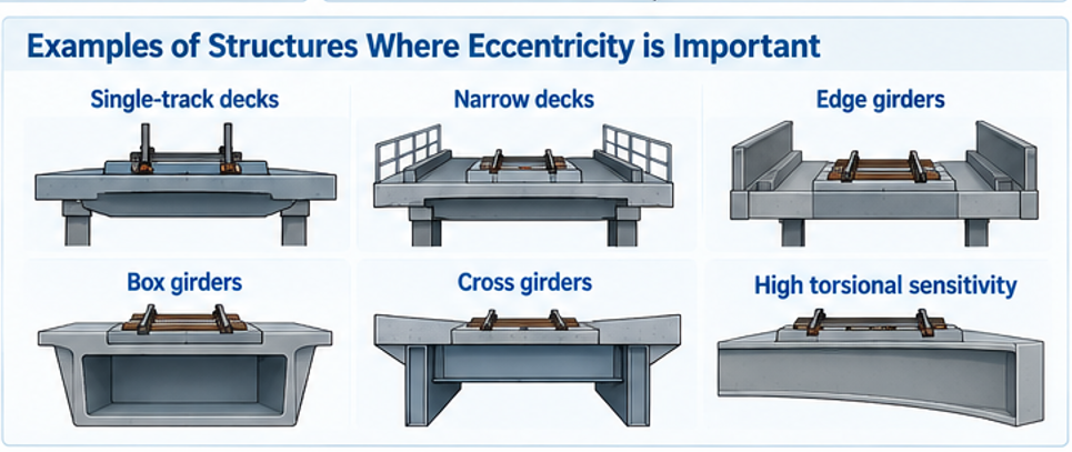
This becomes particularly important for:
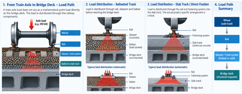
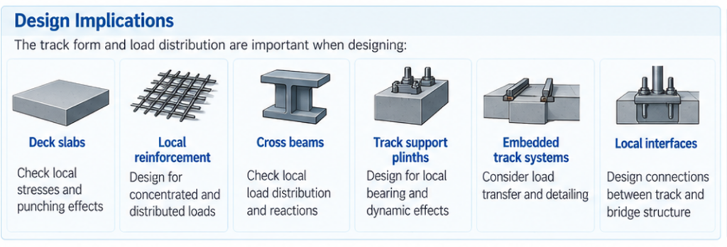
1.7 Distribution of axle loads through the track
A train axle load does not necessarily act as a mathematical point load directly on the bridge deck.EN 1991-2 considers load distribution through railway components such as: Wheel → rail → sleeper/track system → ballast or slab → bridge deck
The resulting structural load distribution depends strongly on the track form.For ballasted track, consideration is given to load distribution through the rail, sleepers and ballast.For slab track/direct fixation systems, the actual project-specific structural arrangement becomes particularly important.
1.8 Dynamic effects
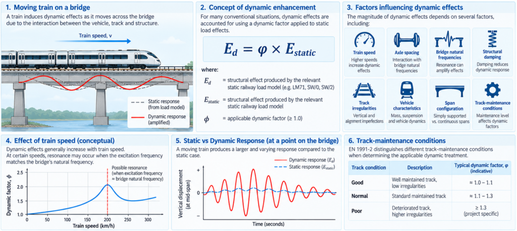
Railway bridges are not designed only for static train loading.A moving train produces dynamic effects resulting from factors including:
- train speed;
- axle spacing;
- bridge natural frequencies;
- structural damping;
- track irregularities;
- vehicle characteristics; and
- span configuration.
EN 1991-2 therefore introduces dynamic enhancement of static railway loading. For many conventional situations, this is handled using specified dynamic factors applied to static load effects.
In conceptual terms:

where:
= structural effect produced by the relevant static railway load model;
= applicable dynamic factor.
The standard distinguishes different track-maintenance conditions in determining the applicable dynamic treatment.
When a dynamic analysis is required?
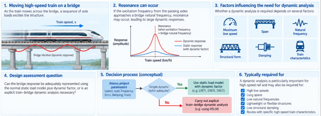
This is particularly important for high-speed rail.A simple dynamic amplification factor is not always sufficient.At higher speeds, the periodic passage of train axles can interact with the natural vibration modes of the bridge.If the excitation frequency approaches a bridge natural frequency, resonance may occur.
Therefore, depending on factors including:
- maximum line speed;
- span;
- natural frequency;
- structural form;
- damping; and
- train characteristics,
a dynamic analysis may be required.
The assessment effectively asks:Can the bridge response be adequately represented using the normal static load model plus dynamic factor, or is explicit train–bridge dynamic analysis necessary?
High-Speed Load Model — HSLM
Where dynamic analysis is required for high-speed railway bridges, EN 1991-2 provides the High-Speed Load Model (HSLM) framework.HSLM is intended to represent the dynamic loading characteristics of high-speed passenger trains without requiring the designer to know every future train that may operate over the route.It contains families of idealised trains/configurations covering relevant combinations of:
- axle spacing;
- coach length;
- axle load; and
- vehicle arrangement.
The objective is to identify potentially resonant structural responses over the required speed range.This is one of the most important differences between conventional railway bridge design and high-speed railway bridge design.

Real trains and dynamic analysis
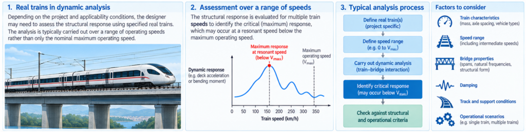
Depending upon the project and applicability conditions, dynamic verification can also involve specified real trains.
The designer may therefore need to assess structural response over a range of operating speeds rather than analysing only the nominal maximum operating speed.
Typically the analysis considers:

because the maximum dynamic response may occur at a resonant speed below the maximum operating speed.
Dynamic response parameters
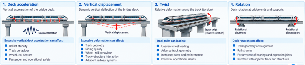
Dynamic analysis is not concerned solely with maximum bending moment.Important responses include:
2 Centrifugal forces
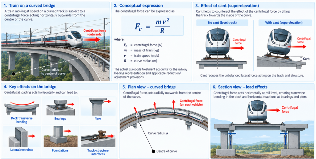
For railway bridges carrying curved track, centrifugal forces must be considered.
Conceptually:

where:
= train speed;
= curve radius.
The actual Eurocode treatment accounts for the railway loading representation and applicable reduction/adjustment provisions.
Centrifugal loading acts horizontally and has implications for:
- deck transverse bending;
- bearings;
- piers;
- lateral restraints;
- foundations; and
- track–structure interfaces.
Cant/superelevation is also relevant to the physical behaviour.
3 Nosing force
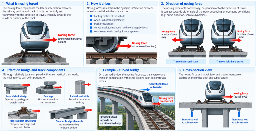
EN 1991-2 includes a nosing force representing lateral interaction between the railway vehicle and track.
This is effectively a transverse horizontal railway action.
Although relatively local compared with major vertical train loads, it can be important for:
- lateral deck design;
- bearings;
- lateral restraints;
- track-support structures; and
- slender bridge elements.
3. Traction and braking forces
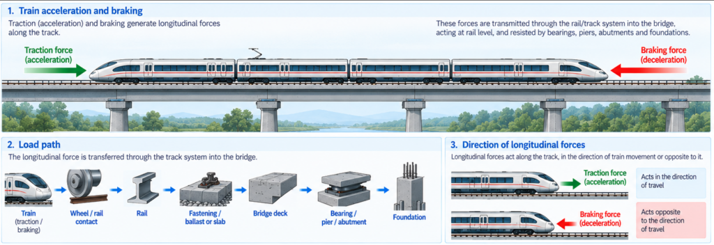
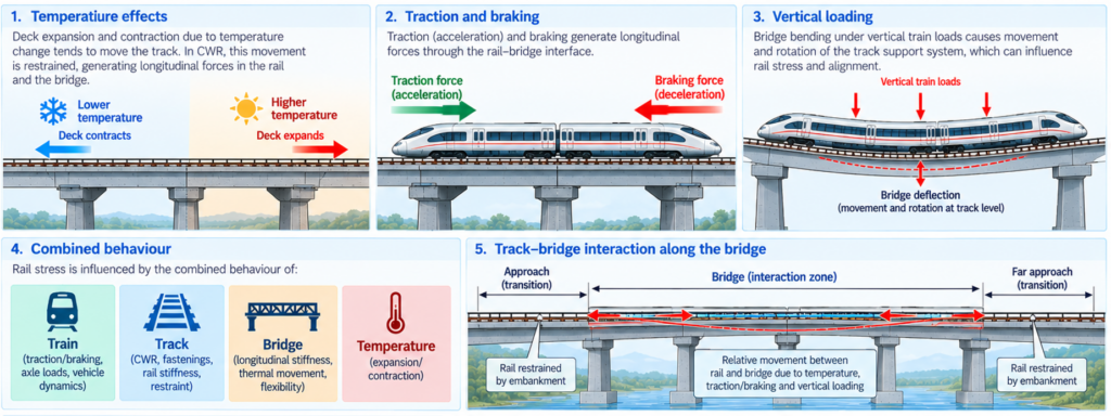
Acceleration and braking generate longitudinal forces along the track.These forces are transmitted through the rail/track system into the bridge.The load path can broadly be represented as: Train → wheel/rail contact → rail → fastening/ballast → deck → bearing/pier/abutment → foundation
This makes traction and braking particularly important for:
- longitudinal bridge design;
- fixed bearings;
- piers;
- abutments;
- foundations; and
- continuous welded rail interaction.
The Eurocode specifies longitudinal actions associated with both traction and braking, including applicable loaded-length considerations.
Track–bridge interaction
For bridges carrying continuously welded rail (CWR), longitudinal bridge behaviour interacts with the track.The important actions include:
Temperature : Deck expansion/contraction tends to move the track.
Traction/braking : Longitudinal railway forces transfer between rail and bridge.
Vertical loading : Bridge bending causes movement/rotation of the track support system.
Consequently, rail stress is influenced by the combined behaviour of:

This may require a dedicated track–structure interaction analysis.
Typical outputs include:
- additional rail stress;
- rail displacement;
- deck displacement;
- longitudinal bearing force; and
- longitudinal substructure reactions.
4 Multiple-track bridges
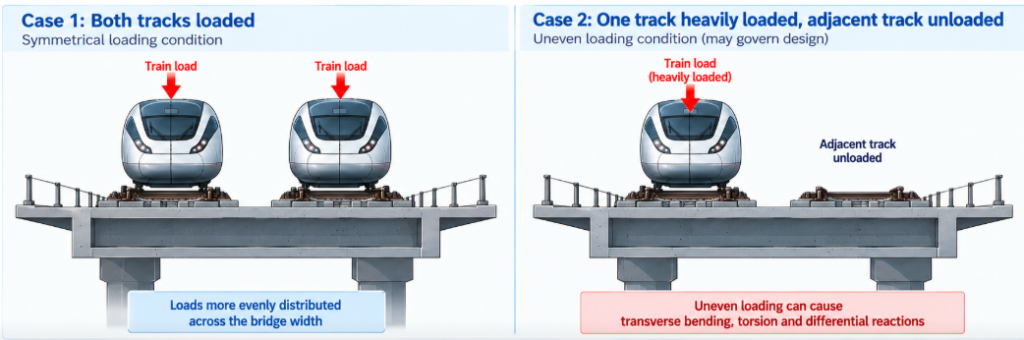
For structures carrying two or more tracks, it is generally unrealistic to assume every track simultaneously experiences its maximum railway loading in every design situation.EN 1991-2 therefore contains rules governing:
- number of loaded tracks;
- positioning of railway loads;
- simultaneous traffic;
- favourable/unfavourable loading; and
- associated reduction considerations.
The designer must establish the governing loading arrangement for each structural effect.
For example:
Pier design : may be governed by both tracks loaded.
Torsion : may instead be governed by one track heavily loaded while the adjacent track is unloaded.
6 Aerodynamic actions from passing trains (Important for High Speed)
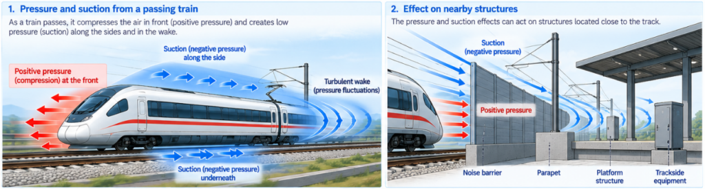
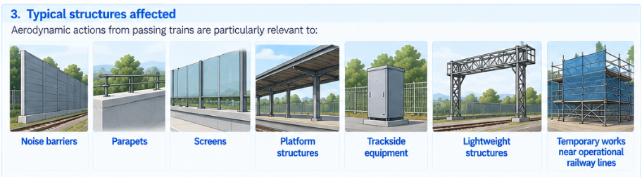
Moving trains generate pressure and suction effects. EN 1991-2 addresses aerodynamic actions caused by passing railway traffic on structures adjacent to the track.These effects are particularly relevant to:
- noise barriers;
- parapets;
- screens;
- platform structures;
- trackside equipment;
- lightweight structures; and
- temporary works near operational railway lines.
The magnitude depends on parameters including:
- train speed;
- distance from track;
- geometry;
- exposed surface; and
- structural arrangement.
This becomes increasingly significant on high-speed lines.
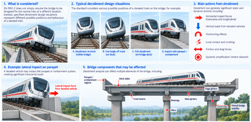
7 Derailment actions
EN 1991-2 contains provisions for the accidental situation of a train derailing on a bridge.The philosophy is not simply:
Design the bridge for the normal train at a different location.Instead, specified derailment design situations are considered.
These represent different possible positions/behaviour of a derailed train and are intended to check that derailment does not cause disproportionate structural failure.
The analysis can affect:
- deck slabs;
- edge girders;
- main girders;
- cross beams;
- parapet/containment regions;
- bearings;
- piers; and
- overall bridge stability.
Accidental design philosophy
Derailment is treated differently from normal railway traffic because it represents an accidental design situation.
The objective is structural robustness and avoidance of catastrophic consequences rather than normal operational performance.
This distinction affects the applicable:
- load representation;
- load combinations;
- partial factors; and
- acceptance criteria.
The Eurocode basis of design and project National Annex therefore need to be read alongside EN 1991-2.
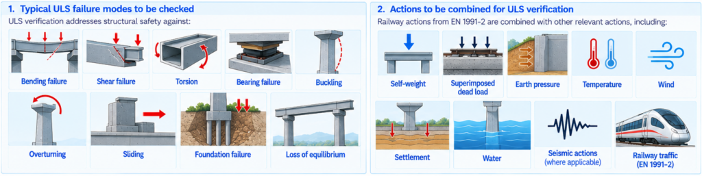
8 Ultimate Limit State — ULS
ULS verification addresses structural safety against conditions such as:
- bending failure;
- shear failure;
- torsion;
- bearing failure;
- buckling;
- overturning;
- sliding;
- foundation failure; and
- loss of equilibrium.
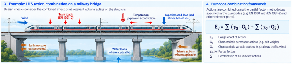
The railway actions from EN 1991-2 are combined with other relevant actions under the Eurocode combination framework.
These may include:
- self-weight;
- superimposed dead load;
- earth pressure;
- temperature;
- wind;
- settlement;
- water;
- seismic actions, where applicable; and
- railway traffic.
9 Serviceability Limit State — SLS
SLS is exceptionally important for railway bridges.A bridge can possess adequate structural strength but still be unsuitable for railway operation if it is excessively flexible. Typical considerations include:
- vertical deck deflection;
- longitudinal displacement;
- transverse displacement;
- deck twist;
- end rotation;
- vibration;
- passenger comfort;
- track geometry; and
- rail stresses.
For high-speed lines, these checks can become as influential as conventional strength design.
9.1 Passenger comfort
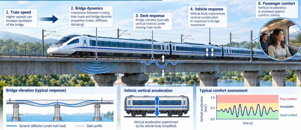
Bridge vibration can influence passenger comfort. EN 1991-2 provides a framework for assessing vertical acceleration of railway vehicles/bridge response and associated comfort considerations. The relevant comfort requirement depends on the project and railway performance criteria.
This establishes an important chain: Train speed → bridge dynamics → deck response → vehicle response → passenger comfort
Consequently, increasing structural strength alone does not necessarily resolve a railway bridge performance issue.
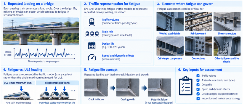
9.2 Fatigue
Railway bridges experience very large numbers of repeated load cycles during their design lives. Fatigue therefore requires separate consideration. Traffic representations for fatigue are intended to reflect repeated railway loading rather than simply applying the maximum ULS train indefinitely.
Fatigue assessment can govern:
- welded steel details;
- reinforcement;
- shear connectors;
- orthotropic components;
- connections; and
- other fatigue-sensitive structural details.
The traffic volume, train mix and design life become important inputs.
Railway designer’s practical checklist
For a railway bridge, a useful EN 1991-2 design workflow is:
| Check | Typical EN 1991-2 consideration |
| Normal vertical traffic | LM71 |
| Continuous bridge | SW/0 where applicable |
| Heavy traffic | SW/2 where specified |
| Route loading | α classification |
| Dynamic amplification | Φ factors |
| High-speed response | Dynamic analysis/HSLM where required |
| Curved track | Centrifugal action |
| Lateral train action | Nosing |
| Longitudinal action | Traction/braking |
| CWR | Track–bridge interaction |
| Multiple tracks | Simultaneous loading rules |
| Passing high-speed trains | Aerodynamic pressure |
| Accident | Derailment situations |
| Operational performance | Deflection/rotation/twist |
| Dynamic performance | Deck acceleration |
| Passenger performance | Comfort |
| Repeated traffic | Fatigue |
| Structural safety | ULS combinations |
| Operational/service behaviour | SLS combinations |
The key engineering message
EN 1991-2 is much broader than a “train loading standard.” For railway structures it establishes a framework in which the bridge must function as part of a dynamic train–track–structure system.
For a conventional bridge, LM71 plus the applicable dynamic factor may dominate much of the structural design. For a high-speed railway bridge, however, the critical engineering issues can shift toward dynamic response, resonance, deck acceleration, deformation, track–bridge interaction, rail stresses, braking/traction forces and passenger comfort.
That distinction is particularly important when developing the structural/interface requirements for a high-speed railway: specifying simply “Design railway loading: LM71 in accordance with EN 1991-2” is not, by itself, a complete railway bridge design requirement.
Key Topics
Railway traffic load models (LM71, SW/0, SW/2 and HSLM); classification factor; load distribution; dynamic amplification and high-speed dynamic analysis; centrifugal and nosing forces; traction and braking forces; multiple-track loading; track–bridge interaction; aerodynamic effects from passing trains; derailment actions; fatigue; bridge deformation and vibration; deck acceleration; passenger comfort; and ULS/SLS traffic load considerations.
Who Uses This Standard?
Used by bridge and structural engineers, railway civil engineers, track engineers, systems/interface engineers, designers, consultants, contractors, infrastructure managers, checking engineers and approving authorities involved in the design, assessment and verification of railway bridges, viaducts and other traffic-carrying structures.
Obtain the Official Standard
RailBays provides an independent engineering overview for reference and educational purposes. For complete normative requirements, always refer to the official current edition issued by the relevant standards organisation or authorised distributor.
View Official Standard ↗