
Introduction
Two rails separated by a fixed distance may be the most recognisable feature of a railway, but railway track is much more than the surface on which trains run.
A modern track is a carefully engineered system that must guide a train travelling at speed, transfer repeated wheel loads into the ground or supporting structure, control vehicle movement through curves, accommodate temperature changes, maintain extremely precise geometry and continue performing under millions of loading cycles.
For a track engineer, therefore, the fundamental question is not simply:
“What components make up a railway track?”
A more useful question is:
“How does the complete track system safely guide and support a moving train?”
Understanding this principle provides the foundation for almost every aspect of track engineering.
The Engineering Purpose of Railway Track
Railway vehicles differ fundamentally from road vehicles because the steering path is provided by the infrastructure.The wheel–rail system guides the train along a predetermined alignment. This means that relatively small variations in rail position can influence vehicle behaviour, passenger comfort, wheel and rail wear and, ultimately, operational safety.
The track must perform several functions simultaneously.It must:
- provide a continuous running surface;
- guide the vehicle laterally;
- maintain the required track gauge;
- transfer vertical wheel loads;
- resist lateral forces generated by vehicle movement;
- resist longitudinal traction and braking forces;
- accommodate thermal forces in the rails;
- maintain the designed horizontal and vertical alignment;
- provide sufficient resilience;
- support safe operation at the required speed; and
- allow inspection, maintenance and eventual component replacement.
These requirements make railway track both a structural system and a precision geometric system.

Following a Wheel Load Through the Track
One of the simplest ways to understand track engineering is to follow the load from the train into the supporting infrastructure.When a wheel passes over the rail, its load does not act only at one isolated point.The rail bends and distributes that load along its length. The fastening system transfers forces from the rail into the sleeper, baseplate or concrete support. These components then distribute the forces over a progressively larger area.
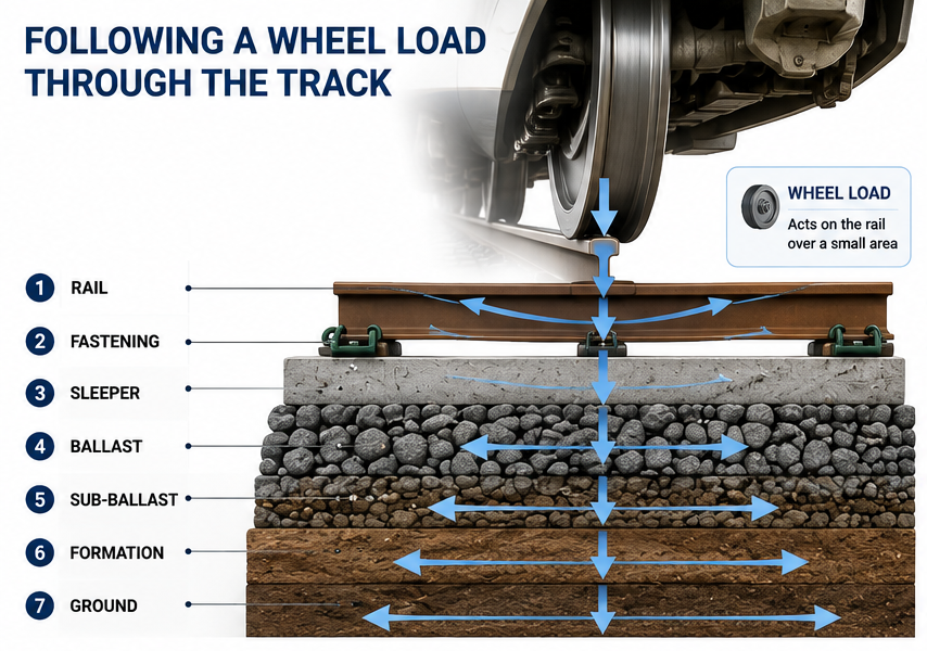
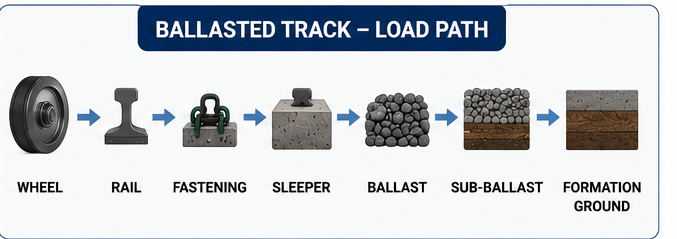
For conventional ballasted track, the load path can be simplified as:
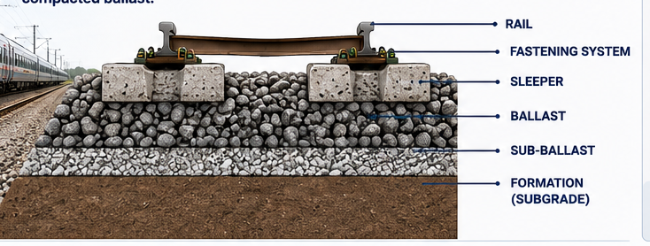
Wheel → Rail → Fastening → Sleeper → Ballast → Sub-ballast → Formation → Ground
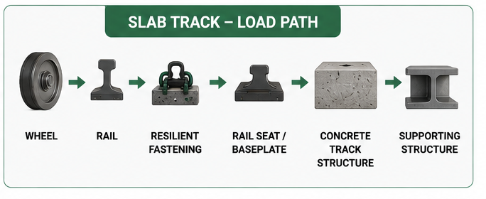
For slab track, it may instead be:
Wheel → Rail → Resilient Fastening → Rail Seat / Baseplate → Concrete Track Structure → Supporting Structure
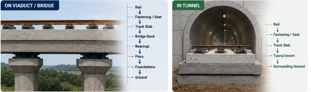
On a viaduct, the load continues through the bridge deck, bearings, piers and foundations.In a tunnel, it may ultimately be transferred through the track slab into the tunnel invert and surrounding ground. This load path is fundamental to track design. Each layer has a specific engineering function, and failure or excessive deformation at one level can affect the performance of the entire track.
The Rail Is Both a Running Surface and a Structural Beam`
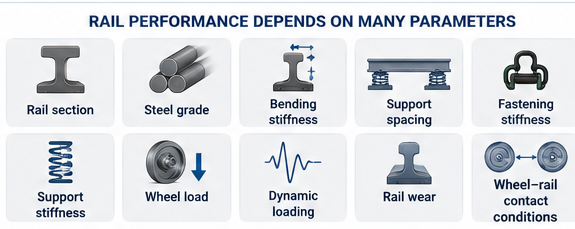
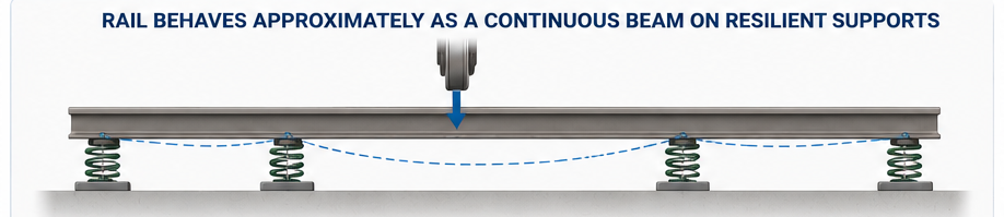
The rail performs several jobs simultaneously.It provides the contact surface for the wheel, guides the vehicle and distributes wheel loads to multiple supporting points.Structurally, a rail behaves approximately as a continuous beam supported by resilient supports.Its performance depends on parameters including:
- rail section;
- steel grade;
- bending stiffness;
- support spacing;
- fastening stiffness;
- support stiffness;
- wheel load;
- dynamic loading;
- rail wear; and
- wheel–rail contact conditions.

This explains why changing one component of a track system can influence other components.For example, increasing fastening stiffness may appear beneficial for controlling rail movement, but it can also change dynamic forces and vibration transmission.
Track components therefore should not be selected independently.
Why Track Needs Resilience
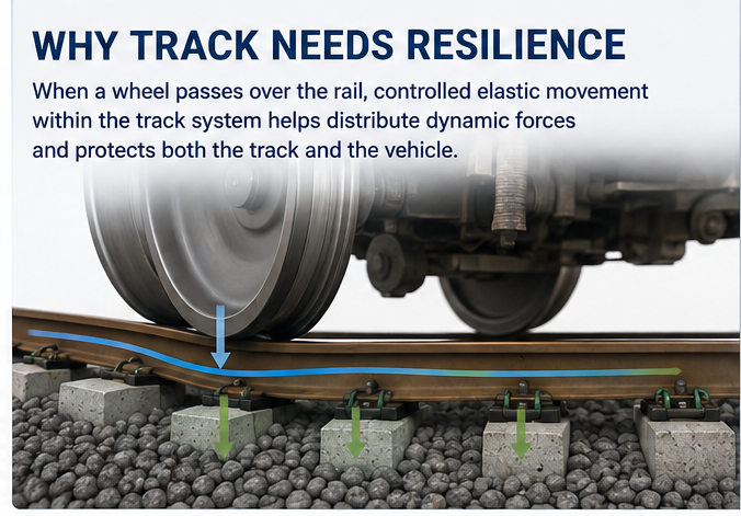
A completely rigid railway track would not necessarily provide the best performance.When a wheel passes over the rail, controlled elastic movement within the track system helps distribute dynamic forces.Resilience may be provided by:
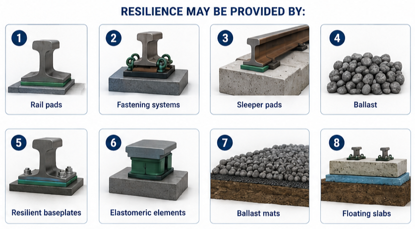
he required stiffness is a design consideration.A system that is excessively stiff may increase dynamic loading and vibration transmission.A system that is excessively flexible may result in excessive rail deflection, poor vehicle behaviour or accelerated component deterioration.
Track engineering therefore involves finding an appropriate balance between:
strength, stiffness, resilience and durability.
Ballasted Track – A Flexible Track Structure
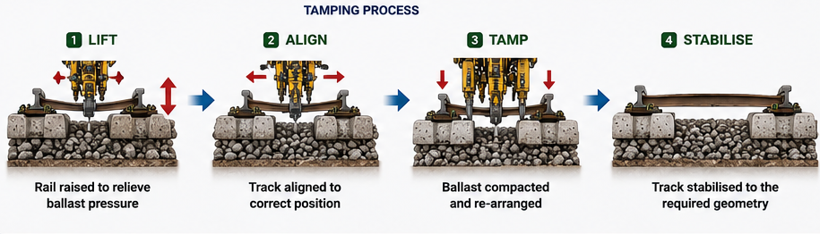
Traditional railway track uses sleepers supported within compacted ballast.The ballast performs several important functions.It distributes loads from sleepers, provides drainage, restrains lateral and longitudinal movement and allows the track geometry to be adjusted through maintenance activities such as tamping.Traditional railway track uses sleepers supported within compacted ballast.The ballast performs several important functions.It distributes loads from sleepers, provides drainage, restrains lateral and longitudinal movement and allows the track geometry to be adjusted through maintenance activities such as tamping.If settlement occurs, the track can often be lifted, aligned and tamped back towards its required position.
However, this flexibility also means that geometry gradually changes under repeated train loading.
Ballast can:
- settle;
- move laterally;
- break down;
- become contaminated;
- lose drainage performance; and
- develop localised defects.

Consequently, ballasted track generally requires periodic geometry maintenance.
Slab Track – Controlling Geometry Through a Rigid Foundation
Slab track takes a different engineering approach.Instead of relying on ballast to support and adjust the track, the rails are supported directly or indirectly by a concrete structure.
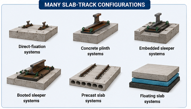
There are many slab-track configurations, including:
- direct-fixation systems;
- concrete plinth systems;
- embedded sleeper systems;
- booted sleeper systems;
- precast slab systems; and
- floating slab systems.
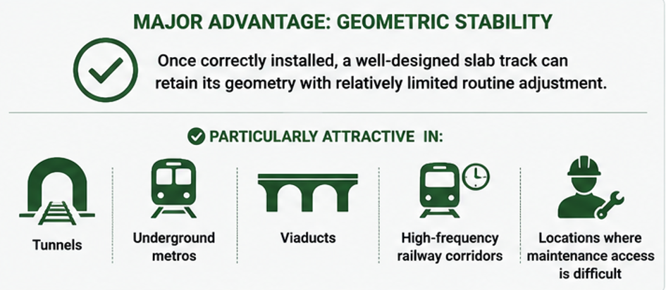
The major advantage is geometric stability.Once correctly installed, a well-designed slab track can retain its geometry with relatively limited routine adjustment.
This is particularly attractive in:
- tunnels;
- underground metros;
- viaducts;
- high-frequency railway corridors; and
- locations where maintenance access is difficult.
But stability creates another engineering challenge.A ballasted track can often accommodate and correct moderate settlement.
A concrete slab cannot easily be tamped.
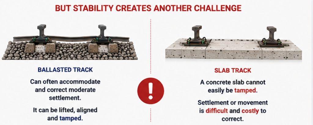
Consequently, the accuracy and stability of the supporting structure become much more important with slab track.

Track Geometry Is Part of the Track System
Track is not simply installed between two geographical points.The rails define a carefully controlled three-dimensional path.The principal geometric parameters include:
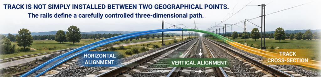
- horizontal alignment;
- curve radius;
- transition curves;
- vertical alignment;
- gradients;
- vertical curves;
- track gauge;
- cant;
- cant deficiency;
- track centres; and
- permitted geometric tolerances.
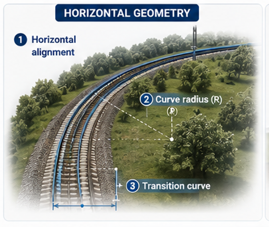
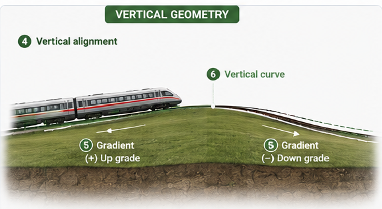
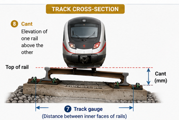
These parameters are strongly linked to train performance.For example, the acceptable radius of a horizontal curve depends partly on operating speed.A train travelling through a curve experiences lateral acceleration. Cant—the elevation of one rail above the other—is introduced to help balance this effect.
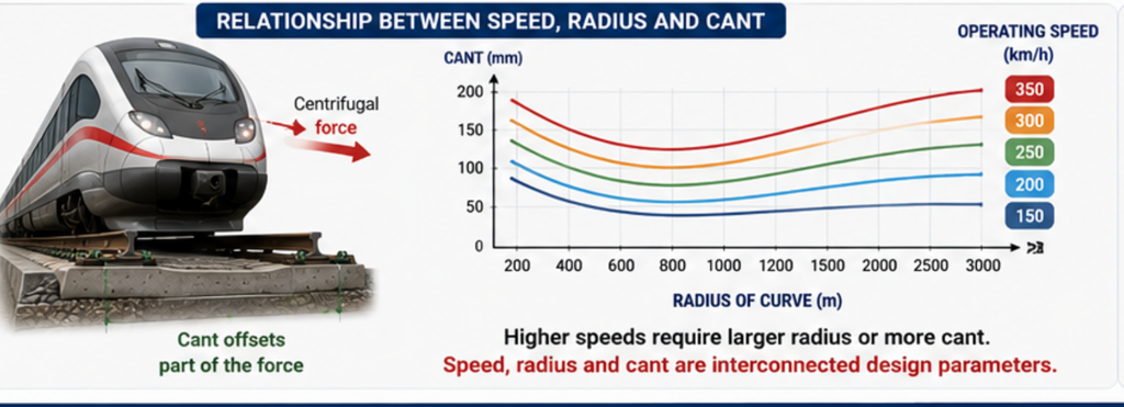
Therefore:speed, radius and cant are interconnected design parameters.
This relationship will be explored in detail in Part 2 of this series.
Track Geometry Begins with the Train
Before defining many track parameters, engineers need reliable information about the rolling stock expected to use the railway.Important information can include:
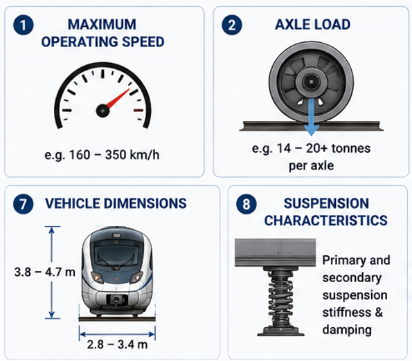
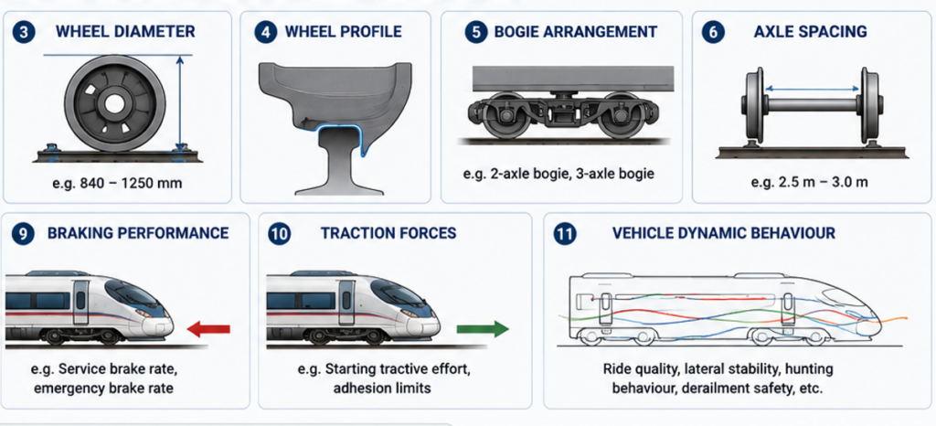
This highlights an important railway interface:Track ↔ Rolling Stock
The infrastructure defines the path followed by the train, but the characteristics of the train influence how that path should be designed.Neither discipline can therefore be fully developed independently.
Continuous Welded Rail Changes the Behaviour of the Track
Historically, rails were installed as relatively short lengths connected by mechanical joints.Modern railways increasingly use Continuous Welded Rail (CWR). Individual rail lengths are welded together to form extremely long continuous rails.
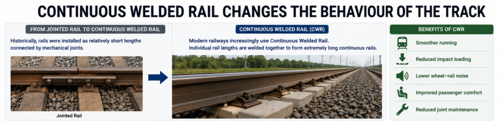
The benefits include:
- smoother running;
- reduced impact loading;
- lower wheel–rail noise;
- improved passenger comfort;
- reduced joint maintenance.
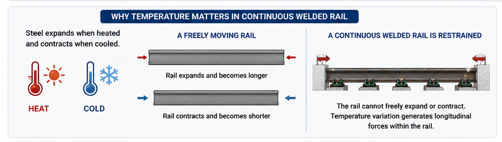
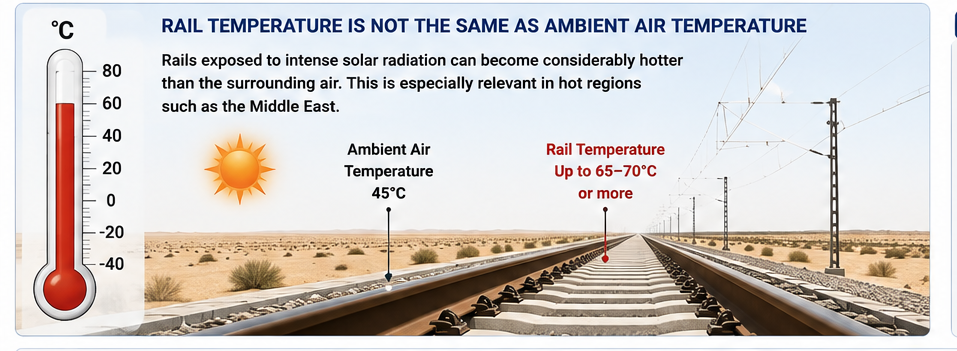
But removing expansion joints introduces an important engineering phenomenon.Steel expands when heated and contracts when cooled.A freely moving rail would simply become longer or shorter as its temperature changed.A continuously welded rail is restrained.Consequently, temperature variation generates longitudinal forces within the rail. At high rail temperatures, compressive forces increase.At low temperatures, tensile forces increase.
If these forces are not properly controlled, potential consequences include:
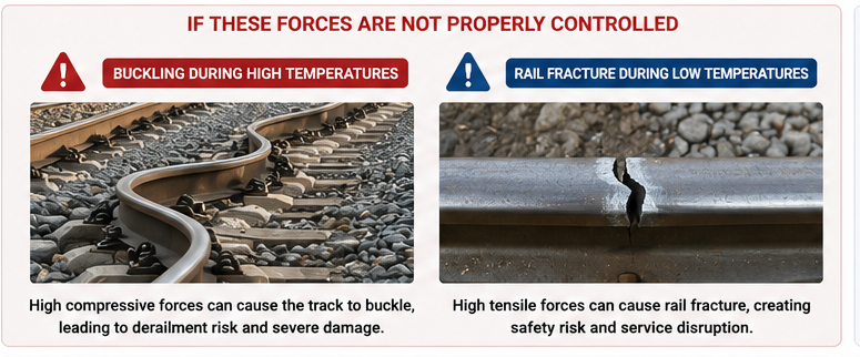
- track buckling during high temperatures; and
- rail fracture during low temperatures.
Rail temperature and stress management are therefore fundamental elements of modern track engineering.
Hot-Climate Railways Require Particular Attention

Rail temperature should not be assumed to be the same as ambient air temperature.Rails exposed to intense solar radiation can become considerably hotter than the surrounding air.This becomes especially relevant in hot regions such as the Middle East.
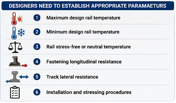
Designers need to establish appropriate parameters including:
- maximum design rail temperature;
- minimum design rail temperature;
- rail stress-free or neutral temperature;
- fastening longitudinal resistance;
- track lateral resistance; and
- installation and stressing procedures.
The issue becomes more complicated where CWR crosses bridges and viaducts because both the rail and the supporting structure respond to temperature.
This leads to another major railway engineering subject:Track–Structure Interaction.
Track on a Viaduct Is Not Simply Track Placed on Concrete
Consider a long railway viaduct.The bridge deck expands and contracts with temperature.At the same time, the continuously welded rails also experience thermal forces.When trains brake or accelerate, longitudinal forces can pass between the rails and the structure through the fastening system.The designer therefore needs to understand how the:
Rail ↔ Fastening ↔ Track Slab ↔ Bridge Deck ↔ Bearings ↔ Piers
interact.This analysis can influence:
- rail stress;
- fastening selection;
- bearing behaviour;
- structural movement;
- expansion-joint arrangements;
- rail expansion devices; and
- allowable deck lengths.
Track–structure interaction is therefore an excellent example of why railway track cannot be designed as an isolated discipline.
The Finished Rail Level Is a Critical Railway Reference
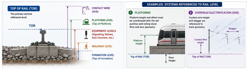
On many railway projects, Top of Rail (TOR) becomes one of the most important reference levels.Numerous other systems are positioned relative to the rails.
Examples include:
Platforms: Platform height and offset must be coordinated with the rail position and rolling-stock floor and door geometry.
Overhead Electrification: Contact-wire height and stagger are referenced to track geometry.
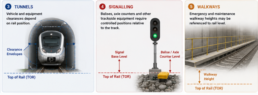
Tunnels: Vehicle and equipment clearances depend on rail position.
Signalling: Balises, axle counters and other trackside equipment require controlled positions relative to the track.
Walkways: Emergency and maintenance walkway heights may be referenced to rail level.
A seemingly small change to track level can therefore affect multiple disciplines.
Track Is an Interface-Intensive Discipline
A track engineer typically coordinates with almost every major railway discipline.Key interfaces include:
Track ↔ Rolling Stock
Wheel–rail interface, axle loads and vehicle dynamics.
Track ↔ Civil Structures
Viaducts, tunnels, stations, bridges and earthworks.
Track ↔ OCS/OLE
Rail level, contact-wire geometry and mast arrangements.
Track ↔ Signalling
Train detection, point machines, balises and trackside equipment.
Track ↔ Traction Power
Return current, bonding and stray-current requirements.
Track ↔ Drainage
Formation drainage, tunnel drainage and track slab drainage.
Track ↔ Operations
Speed, headways, crossovers, turnback arrangements and maintenance access.
This multidisciplinary nature is one of the defining characteristics of railway track engineering.
Why Track Design Must Consider Maintenance
The railway does not remain exactly as constructed.
Over its operating life:
- rails wear;
- wheels apply millions of load cycles;
- ballast settles;
- structures deform;
- fasteners deteriorate;
- rail profiles change;
- drainage systems require cleaning;
- track geometry gradually changes.
Track design therefore needs to consider how the railway will be:
- inspected;
- measured;
- maintained;
- adjusted;
- repaired; and
- renewed.
A design that performs well when newly constructed but cannot be practically maintained is not a successful railway design.
This is why whole-life performance should influence track-form selection.
The Fundamental Track Engineering Principle
For engineers beginning their careers in railways, perhaps the most useful concept is this:
Railway track is the controlled interface between a moving vehicle and fixed infrastructure.
The rails establish the train’s physical path.
Rail + Fastening + Support + Structure + Formation + Geometry + Rolling Stock
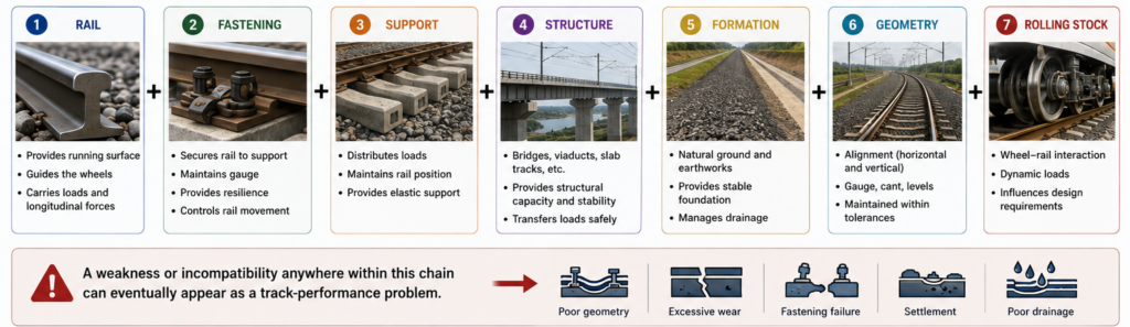
A weakness or incompatibility anywhere within this chain can eventually appear as a track-performance problem.
Understanding the complete system is therefore more important than understanding any individual component in isolation.