

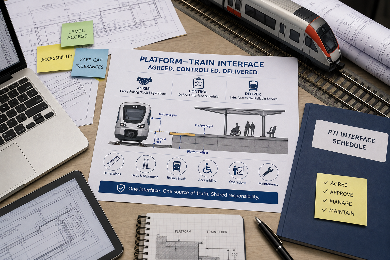
“Mind the gap.”
It is a phrase that will immediately remind many of us of travelling on the London Underground.
Every time I travel on the Tube and hear that familiar announcement, I find myself looking at the platform–train interface and wondering: why can the gap — and sometimes the step — between the train and the platform be so different from one station to another?
It may appear to be a very simple interface, but from an engineering perspective, it is anything but simple.
Platform geometry, track alignment, vehicle dimensions, suspension movement, wheel condition, stopping accuracy, accessibility requirements and railway operations can all influence those few centimetres between the train and the platform.
This is what encouraged me to write this article . From my perspective as an Interface & Integration Manager, PTI is also a very good example of why interface management matters in railway projects. No single discipline can solve it independently. Civil, track, rolling stock, signalling, stations, accessibility and operations all have a part to play.
More importantly, these interfaces need to be identified and managed during design and construction — not discovered when the train finally arrives at the platform for testing.
Ultimately, “mind the gap” should not only be an announcement for passengers.
For railway engineers, it should also be a reminder to design and manage the gap.
Understanding BS EN 16586-2:2025 – Part 1: Designing the Interface for Level and Accessible Boarding
Introduction
For many passengers, boarding a train is an almost unnoticed part of a railway journey. A passenger walks across the platform, steps over the small gap at the doorway and enters the vehicle.
For a wheelchair user, an elderly passenger, a traveller using a walking aid, or somebody with restricted mobility, that same interface can determine whether the railway is independently usable at all.
This seemingly small area between the platform and the train is therefore one of the most important accessibility interfaces in railway engineering.
BS EN 16586-2:2025, Railway applications – Design for PRM use – Accessibility of persons with reduced mobility to rolling stock – Part 2: Boarding aids, addresses this interface from the perspective of boarding aids and their interaction with rolling stock.
But accessibility at the train door cannot be solved by the rolling-stock designer alone.
It is a system-level interface involving:
- rolling-stock floor and doorway geometry;
- platform height and offset;
- track alignment;
- vehicle suspension and loading;
- wheel condition;
- platform curvature;
- stopping position;
- ramps and bridging plates;
- movable steps;
- wheelchair lifts;
- passenger circulation; and
- railway operations.
The engineering challenge is therefore not simply to provide a ramp or lift.
The real objective is to design the railway so that the platform–train interface is inherently accessible wherever reasonably achievable, and to provide a suitable boarding aid where it is not.
Accessibility Is a Railway System Requirement
Accessibility is sometimes treated as an architectural discipline associated mainly with stations: lifts, tactile paving, accessible toilets, ramps and signage.At the platform–train interface, however, accessibility becomes a multidisciplinary railway systems problem.
BS EN 16586-2 forms part of a broader family of European standards dealing with railway design for Persons with Reduced Mobility (PRM). These standards address subjects including contrast, passenger information, optical and friction characteristics, onboard equipment, clearways, access steps, boarding aids and obstacle-free infrastructure routes.
Consequently, compliance cannot normally be demonstrated by checking one component in isolation. Consider a train equipped with an excellent automatic bridging plate. The device may satisfy its rolling-stock requirements, but the overall boarding arrangement may still be unsuitable if:
- the platform is too far from the track;
- the platform height varies significantly;
- the platform is sharply curved;
- equipment obstructs the wheelchair manoeuvring area;
- the train cannot stop consistently at the accessible boarding position; or
- the accessible route through the station does not actually reach that location.
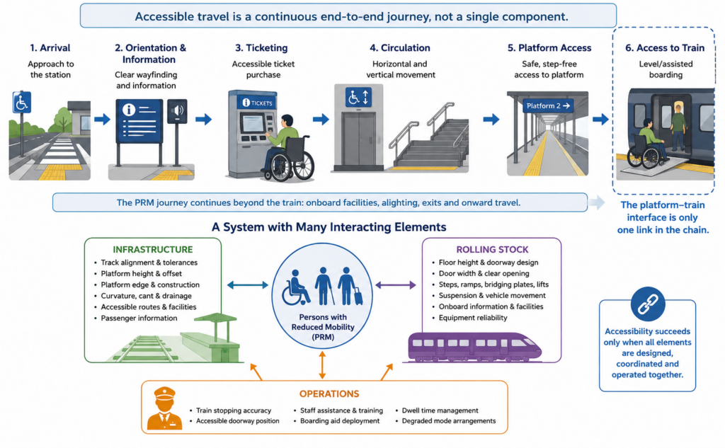
Accessibility therefore has to be treated as an end-to-end passenger journey.
The Rail Baltica station design guidance illustrates this well. Its universal-design philosophy considers the PRM journey from arrival at the station through orientation, ticketing, waiting, horizontal and vertical circulation, access to the platform and finally access to the train.The train doorway is only the final link in that chain.
What Is a Boarding Aid?
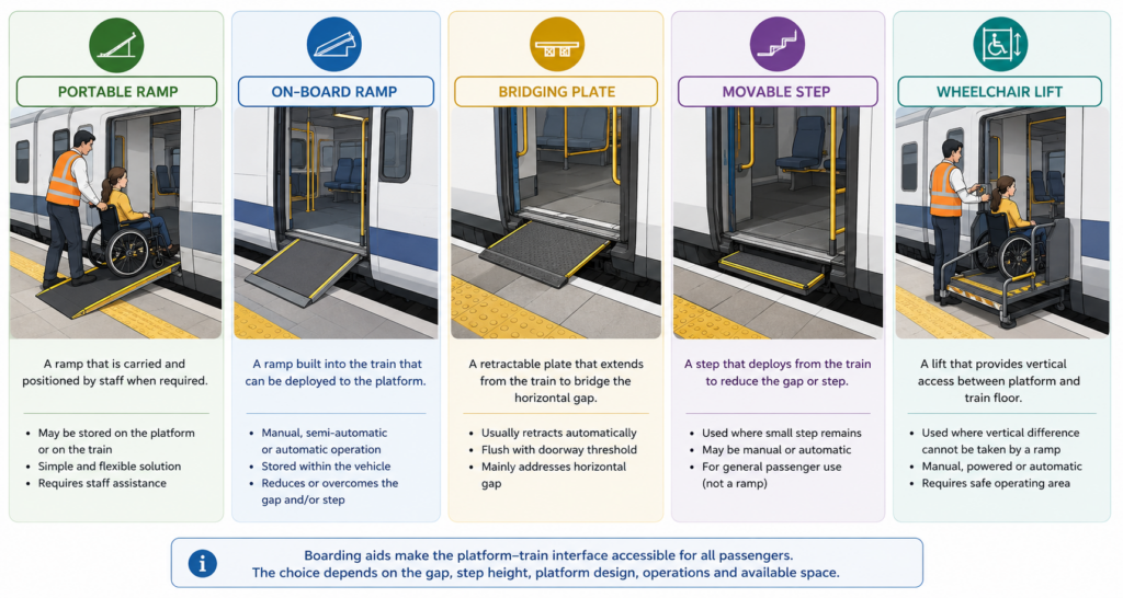
In engineering terms, a boarding aid is a device used to bridge the interface between the rolling stock and the platform so that a person with reduced mobility can board or alight.The principal solutions include:
Portable ramps : A ramp may be stored either on the platform or on the train and positioned by staff when required.
On-board ramps : These are incorporated into the rolling stock and may operate manually, semi-automatically or automatically.
Bridging plates : These are retractable devices incorporated close to the vehicle doorway threshold. They extend toward the platform to reduce or bridge the horizontal interface.
Movable steps: These deploy from the vehicle to reduce the gap or step encountered by passengers. Their purpose is not necessarily identical to a wheelchair bridging plate.
Wheelchair lifts: Where the vertical difference between the platform and vehicle floor cannot reasonably be overcome using a ramp, a lift can provide the required change in level.
Each solution introduces different mechanical, structural, electrical, operational and maintenance interfaces.The first engineering question should therefore not be: Which boarding aid should we install?
It should be: Can the infrastructure and rolling stock first be designed to provide level access?
Level Access Should Be the Starting Point
BS EN 16586-2:2025 establishes a particularly important concept for wheelchair-accessible doorways.
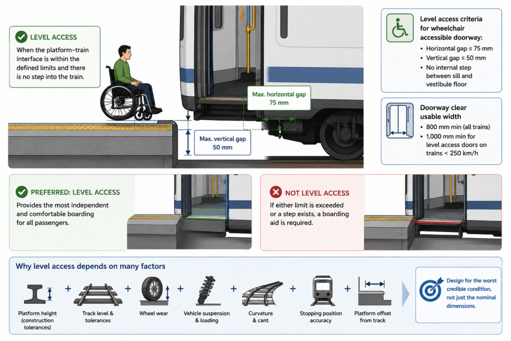
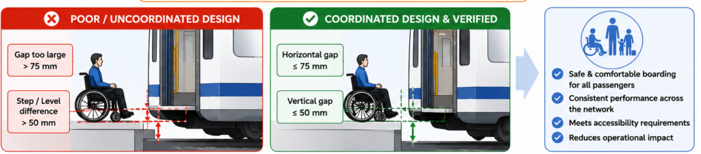
Level access is achieved where the interface between the doorway — or its extended bridging plate — and the platform remains within defined horizontal and vertical limits, with no internal step between the doorway sill and vestibule.
The key limits are:
| Parameter | Level-access criterion |
|---|---|
| Maximum horizontal gap | 75 mm |
| Maximum vertical gap | 50 mm |
| Internal step between sill and vestibule | None |
If those conditions cannot be achieved, a boarding aid complying with the applicable requirements is required.These apparently simple numbers have significant consequences for railway design.
A horizontal gap is affected by:
- platform offset;
- vehicle width;
- kinematic envelope;
- track tolerances;
- platform construction tolerances;
- vehicle suspension;
- lateral movement;
- track curvature; and
- wheel/rail geometry.
The vertical difference is similarly influenced by:
- platform height;
- rail level;
- track tolerances;
- wheel wear;
- suspension condition;
- vehicle loading;
- cant; and
- construction and maintenance tolerances.
The PTI therefore cannot be checked only against nominal CAD dimensions.
Nominal geometry is not operational geometry. That distinction is fundamental.
Absolute Dimensions, Not Convenient Design Targets
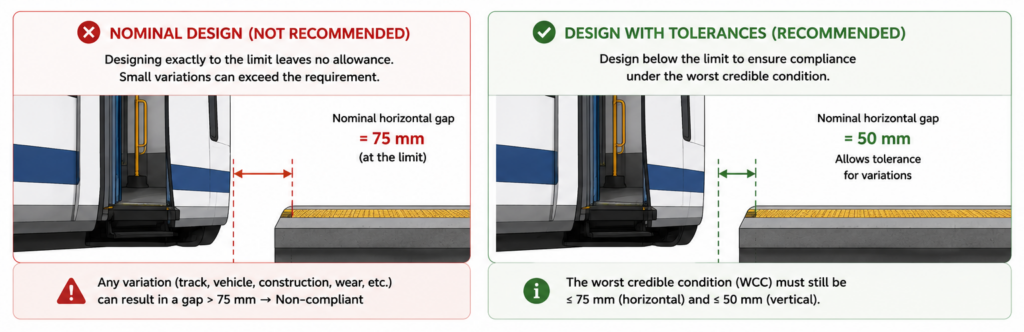
An important principle within EN 16586-2 is that quoted minimum and maximum dimensions are absolute rather than nominal requirements.This changes how engineers should approach design.Suppose a design simply specifies:
Horizontal platform-to-train gap = 75 mm.
If 75 mm is the maximum permitted value, designing the nominal interface at exactly 75 mm provides effectively no engineering tolerance.Construction variation, rail wear, suspension movement or track position could immediately push the operating condition beyond the limit.Good engineering therefore requires a tolerance study.
Instead of asking: “Does the nominal drawing show 75 mm?”
the designer should ask:
“What is the worst credible horizontal and vertical interface throughout the operating envelope?”
That calculation should consider the appropriate combinations of infrastructure and vehicle tolerances.This is particularly important on projects where the civil works and rolling stock are procured under different contractsThe civil contractor may design the platform against a reference vehicle.. The rolling-stock contractor may subsequently develop a vehicle against a reference platform.Unless those two reference geometries and their tolerances are controlled through a formal interface, both designs may individually appear compliant while the completed railway is not..
Platform Geometry and Rolling Stock Must Be Designed Together
The platform–train interface is one of the clearest examples of why railway interface management matters.The infrastructure designer controls parameters such as:
Infrastructure
- track alignment;
- platform height;
- platform offset;
- platform curvature;
- cant;
- platform edge construction;
- trackform tolerances;
- platform construction tolerances.
The rolling-stock designer controls:
- vehicle width;
- floor height;
- door threshold;
- suspension characteristics;
- wheel diameter;
- doorway dimensions;
- bridging plate;
- movable step;
- boarding ramp or lift.
Operations introduce another set of parameters:
Operations
- stopping accuracy;
- train formation;
- accessible doorway location;
- staff assistance;
- deployment procedures;
- dwell time;
- degraded-mode arrangements.
The accessible boarding solution exists at the intersection of all three.
For this reason, the PTI should normally be treated as a formally managed civil–rolling stock–operations interface.
Curved Platforms Make the Problem Harder
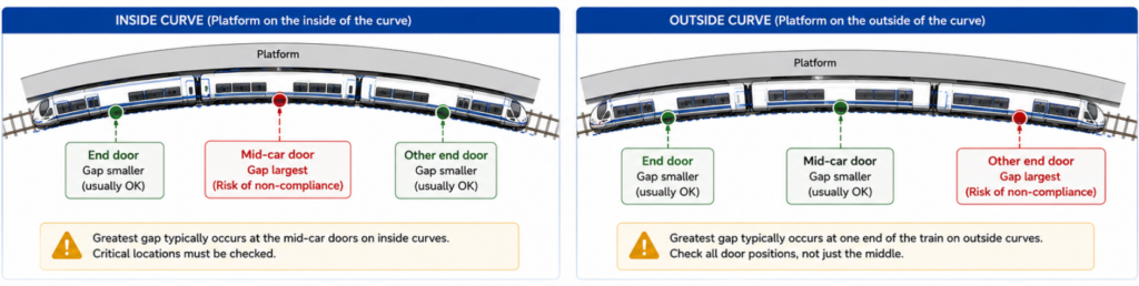
Straight platforms provide the simplest geometry. Curved platforms can significantly increase the horizontal distance between the train and platform at particular door locations.Depending on whether the platform is on the inside or outside of the curve, different portions of the vehicle can move farther away from the platform edge.Vehicle geometry, bogie spacing, body overhang and track curvature therefore influence the actual gap.
This explains why platform–train interface assessment should not rely solely on a typical cross-section. BS EN 16586-2 includes assessment conditions involving both straight track and curved track, including assessment associated with a 300 m curve.
For major railway projects, PTI verification should consequently consider the relevant worst-case locations rather than assuming that one representative platform section demonstrates compliance for an entire network.
Door Width Is Part of Accessibility
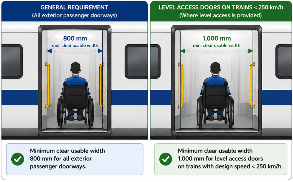
The gap is only one part of accessible boarding.The passenger must also be able to pass through the doorway.BS EN 16586-2:2025 establishes a minimum clear usable width of: 800 mm for exterior passenger doorways. Importantly, this is clear usable width. Handrails, door edges, lift mechanisms or other equipment cannot simply occupy part of that minimum envelope.
For trains with a design speed below 250 km/h that provide level access at the wheelchair-accessible doorway, the standard requires a larger minimum clear usable width of:1,000 mm.There is a practical reason for this.Without a ramp or similar boarding device guiding the wheelchair toward the doorway, the wheelchair may approach the opening at an angle rather than perfectly perpendicular to it. Additional width reduces the risk of the wheelchair, passenger or passenger’s hands contacting the doorway equipment.
Accessibility therefore involves not only dimensional compliance but an understanding of how passengers actually move.
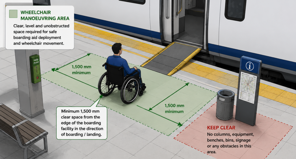
The Wheelchair Manoeuvring Area Must Exist on the Platform
Providing a compliant ramp does little good if a wheelchair cannot approach it.The platform must therefore accommodate the operating envelope of the boarding aid and the passenger.BS EN 16586-2 considers the wheelchair boarding-aid operational zone when assessing ramps.
The Rail Baltica platform guidance provides a useful infrastructure example. Where facilities are provided for wheelchair users to board or alight, it requires an obstacle-free space of 1,500 mm from the edge of the boarding facility in the direction in which the wheelchair boards or lands.
This requirement has consequences for:
- columns;
- benches;
- platform screens;
- information displays;
- signalling equipment;
- drainage;
- lighting columns;
- help points;
- advertising;
- platform shelters; and
- other station equipment.
A platform can therefore be geometrically wide enough for normal passenger circulation while still being unsuitable for deployment of the accessible boarding system.
The boarding zone should be deliberately protected during station layout development.
Ramp Gradient Matters
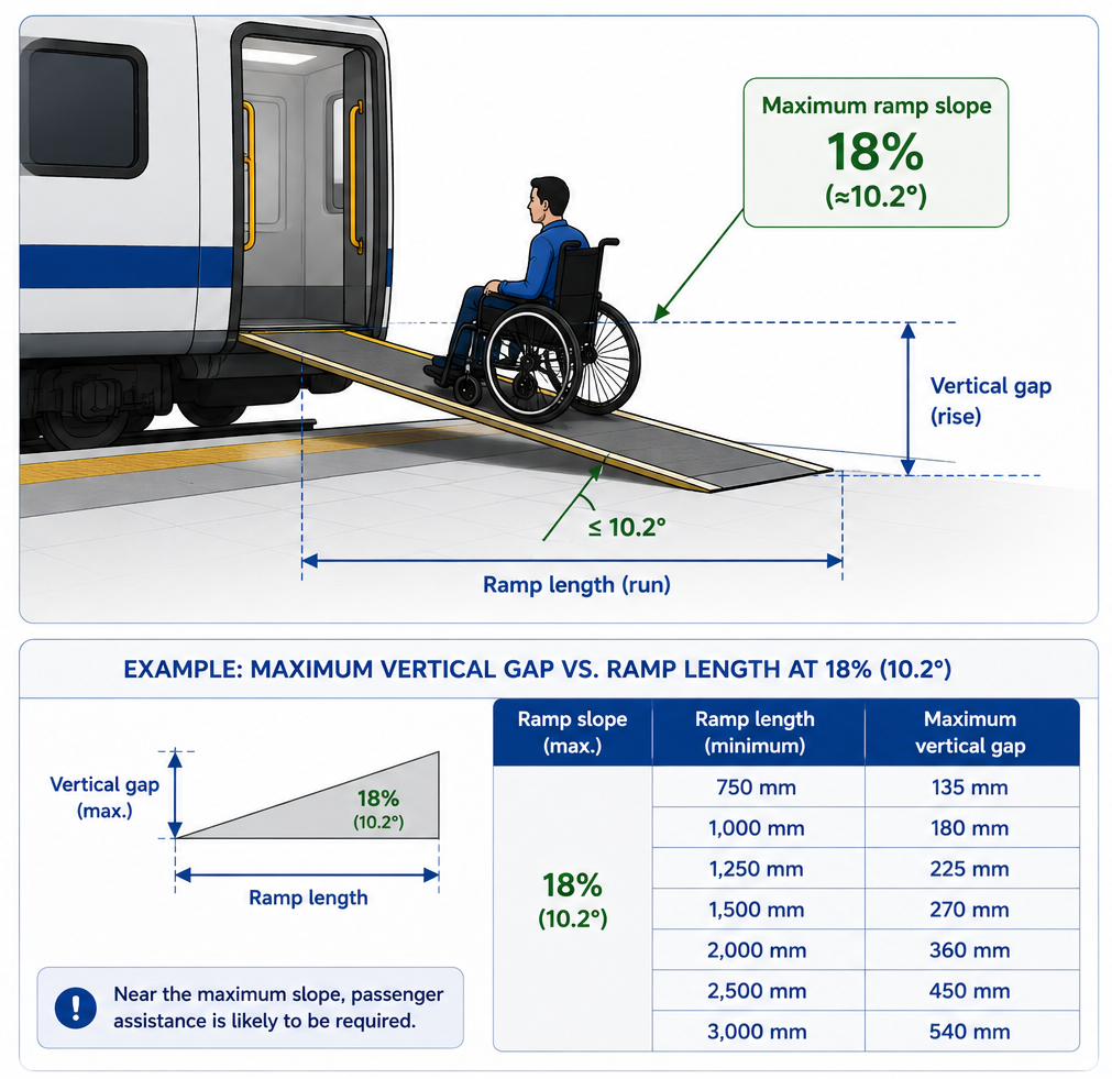
Where level access cannot be provided, ramps are one possible solution.But a ramp is not simply a plate connecting two levels.As the vertical difference increases, either the ramp becomes longer or its gradient becomes steeper.BS EN 16586-2:2025 establishes a maximum ramp slope of: 18% — approximately 10.2°.
The maximum vertical gap that can therefore be accommodated depends directly on the available ramp length. Near the maximum gradient, passenger assistance is likely to become increasingly important. This creates another important systems relationship:
platform height → vertical gap → required ramp length → platform footprint → wheelchair manoeuvring space → station layout.
A rolling-stock decision can therefore influence civil-platform planning several metres away from the vehicle.
Boarding Aids Need Safe Storage
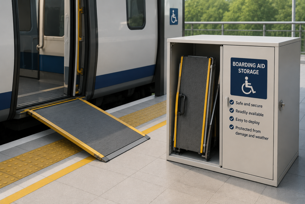
Portable equipment introduces another often overlooked requirement: storage.A portable ramp left against a wall or beside a platform cabinet can itself become an obstruction. Boarding aids stored on platforms therefore require secure arrangements that prevent them from creating hazards for passengers.
Similarly, equipment stored on board the train must be secured so that it cannot interfere with wheelchairs or mobility aids or become hazardous during sudden vehicle movement.This illustrates a recurring railway-design principle:
Accessibility equipment must remain accessible without creating a new accessibility or safety hazard.
The Accessible Route Does Not End at the Platform
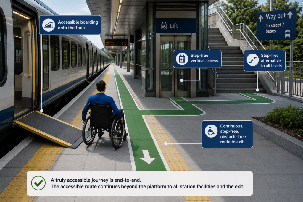
A perfectly designed boarding interface is of little value if the passenger cannot reach it.EN 16586-2 therefore sits within a wider accessibility framework.Infrastructure requirements such as obstacle-free routes are addressed by EN 16587, while other members of the PRM design family address subjects such as contrast, optical characteristics, onboard circulation and passenger facilities.The Rail Baltica station guidance similarly treats accessibility as a continuous journey.
Among its platform provisions are considerations for:
- tactile paving;
- visual warning lines;
- tactile guidance;
- non-slip surfaces;
- unobstructed movement;
- wheelchair spaces;
- accessible waiting areas;
- lifts and ramps;
- audible information; and
- access to the train.
This is the correct systems-engineering perspective.
An accessible railway is not a collection of accessible components.It is an unbroken accessible journey.
A Typical PTI Interface Control Philosophy
For a new railway project, the platform–train interface should ideally have a controlled set of parameters agreed between the infrastructure, rolling-stock and operations teams.
A PTI interface schedule could include:
| Interface Parameter | Primary Parties |
| Platform height above rail | Civil / Track / Rolling Stock |
| Platform offset from track centreline | Civil / Track / Rolling Stock |
| Vehicle floor height | Rolling Stock |
| Door sill geometry | Rolling Stock |
| Horizontal gap | Civil / Track / Rolling Stock |
| Vertical gap | Civil / Track / Rolling Stock |
| Wheel wear allowance | Rolling Stock |
| Suspension movement | Rolling Stock |
| Track tolerances | Track |
| Platform tolerances | Civil |
| Platform curvature | Alignment / Civil |
| Train stopping accuracy | Signalling / Operations |
| Accessible doorway position | Rolling Stock / Operations |
| Boarding-aid type | Rolling Stock / Stations |
| Boarding-aid operating zone | Rolling Stock / Civil |
| Wheelchair manoeuvring area | Stations / Civil |
| Deployment procedure | Operations |
| Maintenance responsibility | Operator / Maintainer |
This information should not remain scattered between rolling-stock specifications, civil drawings, accessibility reports and operating procedures.
It should be controlled as a defined interface.
Verification Should Examine the Worst Credible Condition
A common mistake in railway design is demonstrating accessibility using the most convenient combination of dimensions. The engineering assessment should instead investigate the governing operational combinations. For example:
For example:
Maximum horizontal gap :may result from a particular combination of platform offset tolerance, track position, vehicle displacement and curvature.
Maximum vertical difference may occur with a combination of platform construction tolerance, track level, wheel condition, suspension state and vehicle condition.
The resulting boarding-aid geometry then needs to remain within its allowable operating envelope.This is why EN 16586-2 includes defined assessment conditions rather than relying solely on nominal dimensions. For complex projects, a dedicated Platform–Train Interface tolerance analysis can be one of the most valuable accessibility deliverables produced during design.
Accessibility Is Also an Operational Requirement
Engineering cannot stop when the ramp successfully deploys during factory testing.The system must work during passenger service.Questions should include:
- How does a wheelchair user request assistance?
- How does station or train staff know which doorway requires assistance?
- Who deploys a manual ramp?
- What happens at an unstaffed station?
- How is the boarding position identified?
- What happens if the automatic bridging plate fails?
- Can the train depart if the device has not fully retracted?
- How is equipment inspected?
- How quickly can failed equipment be isolated?
- What alternative arrangement exists during degraded operation?
- Does deployment materially affect dwell time?
These questions sit partly outside the physical dimensions of EN 16586-2, but they determine whether the engineering solution actually delivers accessibility.
What Railway Designers Should Take Away
BS EN 16586-2:2025 should not be viewed simply as a specification for wheelchair ramps.Its wider engineering lesson is more important.The accessibility of a train cannot be separated from the geometry of the railway infrastructure on which it operates.The key principles are:
Design for level access first.
Reducing the fundamental platform–train discontinuity is preferable to relying unnecessarily on operational assistance.
Control the PTI as an interface.
Platform geometry and vehicle geometry must be developed against common parameters.
Design against tolerances, not just nominal dimensions.
Maximum and minimum requirements need to remain satisfied under the applicable assessment conditions.
Protect the boarding zone.
The platform must provide sufficient unobstructed space for boarding-aid deployment and wheelchair manoeuvring.
Consider operations early.
A technically compliant boarding aid that requires an impractical operating procedure is not a well-integrated railway solution.
Think about the complete passenger journey.
Accessibility starts before the passenger reaches the platform and continues after the passenger enters the train.
Conclusion
The distance between a railway platform and a train may be measured in millimetres, but its consequences are much larger. For some passengers it represents nothing more than a small step. For others it determines whether the railway can be used independently.BS EN 16586-2:2025 provides engineers with requirements and assessment methods for managing this critical interface through level access and, where necessary, boarding aids.
The strongest railway designs, however, go beyond treating accessibility as equipment added late in the project. They integrate rolling stock, track, platforms, stations and operations from the beginning.
That is ultimately the difference between providing an accessible component and designing an accessible railway.
Refernce : RBDG-MAN-026-0104_StationsAndPassengerPlatforms
Down load the Standard: BS EN 16586-2:2025 – TC | 31 Oct 2025